Telephone/WhatsApp:+86 156 2656 0610
Telephone/WhatsApp:+86 156 2656 0610
Email:info@seekmach.com

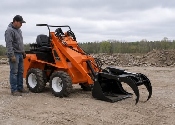
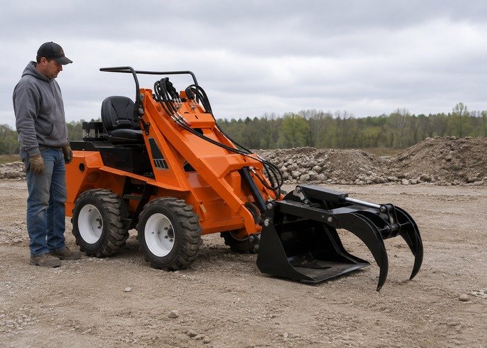
A skid steer attachment that moves in only one direction has a directional-flow problem, not automatically a failed attachment. The cause may be control mode, a hose connected to the wrong port, a coupler that is only partly open, trapped back pressure, a blocked return, missing case drain, damaged hose, electrical solenoid fault, sticky valve spool, cylinder trouble, or motor damage.
Lower the attachment, stop the engine, remove the key, relieve auxiliary pressure by the loader manual, and keep hands away from leaks. The NIOSH hydraulic safety guidance applies: never use a finger to locate a leak, and treat suspected injection as an emergency.
Define the failure precisely. Does a grapple open but not close, a broom turn forward but not reverse, or a cylinder move only when the switch is held one way? Record attachment, coupler position, flow mode, engine speed, oil temperature, fault codes and whether swapping direction changes engine load.
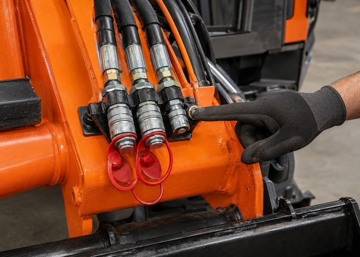
Read the loader and attachment manuals together. Some machines have momentary, variable and continuous-flow modes; some assign direction to a thumb switch; others reverse flow at the couplers. Verify hydraulic unlock, seat bar, interlocks and auxiliary enable. A control not moved through full travel can command low or zero flow one way.
The auxiliary control manual example shows how variable and maximum-flow modes differ. Its buttons and sequence are model-specific. Retrieve codes and live switch percentages where available before disconnecting power.
Label pressure A, pressure B, motor return, tank return and case drain from the attachment diagram. Two large work hoses generally reverse direction; a smaller case drain carries leakage to tank and must never be used as the main return. A free-return line may also have special back-pressure limits.
Confirm the attachment demand against the skid steer auxiliary hydraulic flow guide. Flow, maximum pressure, return pressure and case-drain allowance all matter. An attachment can fit the universal plate yet remain hydraulically incompatible.
Clean each face and verify matching profile, size and rating. A sleeve can lock while a damaged poppet remains partly closed. Look for dented noses, displaced seals, corrosion, dirt, heat discoloration and a hose pulling sideways. Relieve both sides before disconnecting.
Follow the safe connection sequence in the loader operating manual example. It also illustrates case-drain identification and warns that leaving auxiliary control in flow when unused can overheat oil.
An attachment may move in the direction that pressurizes the healthy hose but stall when oil must return through a restricted coupler. Compare hose firmness and system sound from the seat; do not touch a pressurized line. A return restriction often creates rapid heat, noise or seal leakage.
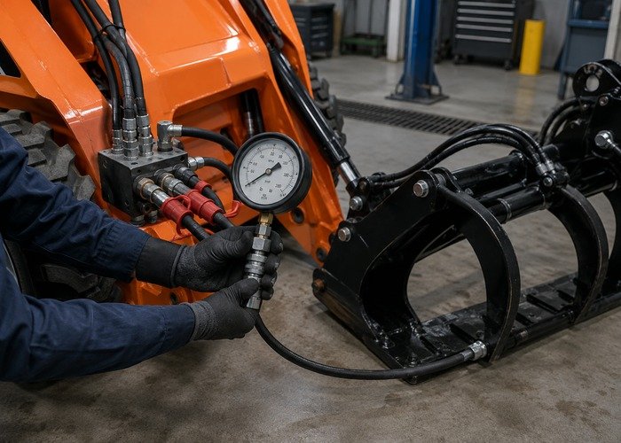
Use rated gauges at specified test points. Measure supply and return pressure in each direction at the same oil temperature and engine speed. Never substitute a low-pressure gauge on a circuit that can reach relief pressure. The auxiliary hydraulic selection overview explains why matching attachment demand and loader capability matters.
High-speed motors may require a dedicated low-pressure case drain. If it is disconnected, coupled to the wrong port, plugged or routed through an excessive restriction, motor housing pressure can damage shaft seals and make the attachment weak or one-directional. Confirm maximum permitted case pressure from the attachment manual.
Inspect the smaller coupler, hose, tank path and filter. Do not tee a case drain into an unknown return. A technical attachment troubleshooting manual demonstrates how an unengaged or restricted case drain appears in a fault tree.
Test another known-compatible attachment only when the manual permits and both systems are clean. If the second attachment reverses normally, focus on the first attachment. If both fail in the same direction, inspect loader switch input, solenoid current, spool travel, reliefs and couplers.
Use the coupler and hose inspection guide and skid steer attachment compatibility guide to keep interface faults separate from internal component faults.
On electrohydraulic machines, compare command percentage, voltage, ground drop, coil resistance and current in both directions. A switch may command one side of a proportional valve but not the other. Check connectors for backed-out pins, corrosion and harness rub.
A spool can stick because of contamination, mechanical damage or an over-tightened coil nut. Do not pull a cartridge before cleaning the area and obtaining the exact procedure. Record shim locations and settings; changing a relief adjustment to force movement can damage the attachment.
For a double-acting cylinder, inspect rod damage, pin binding and hose routing. Internal seal bypass can reduce force, but one-way failure more often suggests flow path or load-holding components. Manufacturer-approved isolation tests require secure support and rated containment.
For a motor, measure case drain, inlet pressure, return pressure and speed. Excess case flow or metal may indicate wear. Review oil and filter condition through the skid steer maintenance checklist; installing a new motor into contaminated oil repeats the failure.
This video explains hydraulic back pressure around skid steer couplers. Use it to recognize the symptom and safe inspection points, not as a substitute for your loader and attachment manuals.
Keep the attachment lowered and relieve pressure before touching any coupler. A stiff hose is not a pressure gauge.
Confirm the smaller drain or return connection before running a high-flow motor. Never assume the third line is optional.
After the demonstration, map your circuit and write the expected flow direction for each command. This prevents random hose swapping.
Reconnect clean couplers, start at low rpm and test each direction without load. Stop for heat, chatter, leakage or a hose trying to straighten violently.
Repeat at operating temperature only after the low-load test passes. Record pressure, return pressure and case-drain observations.
| Observation | Best next check |
|---|---|
| No engine load in failed direction | Command, solenoid and spool |
| Engine loads heavily | Blocked return, coupler or mechanical bind |
| Works with another attachment | Attachment hoses, valve, cylinder or motor |
| Both attachments fail same way | Loader control, coupler and main valve |
| Seal leaks after test | Case-drain and return pressure |
Verify normal movement both ways, neutral hold, hose clearance and temperature. Add the new path to the skid steer buyer and ownership guide when evaluating used equipment.
Prepare a circuit sheet before connecting gauges. Draw the loader A and B work ports, any tank return, case drain, attachment valve, cylinder or motor, and relief valves. Mark the expected pressure and return path for each control direction. This simple map prevents a common mistake: assuming the hose that becomes firm is necessarily the healthy pressure line when it may be a blocked return.
Begin with oil at the manual’s test temperature and the attachment unloaded. Time a fixed movement in each direction and record engine rpm, command percentage, supply pressure, return pressure and case pressure. Do not hold a stalled attachment against relief longer than the service procedure allows. Excessive stall time heats oil and can turn a diagnostic test into component damage.
If the loader offers standard and high flow, verify the selected mode against the attachment plate. High flow does not cure a directional fault and may overspeed a motor designed for standard flow. Likewise, continuous detent is not required for every cylinder attachment. Select the mode specified by the attachment maker, then prove directional response at low flow first.
Inspect hose behavior without touching it. A hose that jumps or straightens sharply can reveal pressure, but observers must remain clear. Use remote cameras or a second trained operator if visibility is poor. Never route a person between the loader and attachment while controls are enabled. Lower the arms or use the manufacturer’s mechanical support for any approved service position.
When contamination is suspected, preserve evidence. Capture a clean oil sample and inspect the filter using the correct method. Metallic debris, elastomer fragments or varnish may point toward motor, cylinder or valve damage. Do not flush debris from one component into another. Plan component cleaning, hose replacement, reservoir service and filter changes as one contamination-control job.
After a repair, verify more than motion. Confirm smooth speed in both directions, neutral holding, normal return pressure, acceptable case drain, stable oil temperature and no leakage. Test the attachment through its working range while watching hose bend radius and coupler alignment. Recheck mounting pins and the quick-attach lock before lifting material.
Give the operator a concise stop rule: if a function becomes one-directional, slows abruptly, squeals, heats a coupler or pushes oil past a seal, lower the attachment and stop. Continuing to hold the failed command can overheat oil, rupture a hose or pressurize a motor housing. Early shutdown preserves the evidence needed for an accurate repair.
Store the completed A/B readings with the attachment serial number and loader used. The same attachment may behave differently on a machine with another coupler profile, flow range or return arrangement. A portable record prevents the symptom from being misdiagnosed when equipment is swapped across a fleet.
Provide both serial numbers, coupler standard, standard- or high-flow setting, rated flow, relief pressure, required return pressure, case-drain limit, electrical connector type and the exact failed direction. Include pressure and case-drain readings rather than only a video. This lets support staff distinguish compatibility, control and internal attachment faults.
Ask whether the attachment uses a crossover relief, check valve, counterbalance valve or pilot-operated valve that could block one direction. Request a hydraulic schematic and test conditions. Do not remove cartridges based on appearance; valves with the same body may have different pressure settings and internal functions.
For fleet use, make a compatibility card for every loader-attachment pair. Record plate fit, hydraulic flow range, coupler profile, drain requirement, electrical controls, hose length and verified operating direction. A green mechanical fit does not mean hydraulic compatibility. Quarantine combinations that lack a safe return or case-drain path.
The final acceptance run should reproduce the original work at gradually increasing load while monitoring temperature. Confirm both directions, expected speed, neutral hold, normal sound and clean couplers. Inspect the attachment again after shutdown and pressure relief. A repair passes only when it remains stable warm and under realistic load.
If the fault is intermittent, repeat the test after vibration and several direction changes. Watch whether failure follows a particular switch position, hose bend, attachment angle or oil temperature. Preserve the exact sequence; an electrical pin, sticky spool, damaged poppet or collapsing hose can appear normal after the machine is parked for service.
Document any substitution used during diagnosis and restore the original safe configuration. Do not leave temporary test adapters, disabled interlocks or improvised return routing on a production loader. Fit caps, guards and hose restraints, then verify attachment locking before release.
Retest with the attachment empty before applying a normal working load. Compare extend and retract time, sound, oil temperature and return pressure. If the symptom changes with load, do not assume the coupler repair is complete; a cylinder piston seal, motor wear or relief setting may still be involved. Record the loader and attachment serial numbers so the next technician can reproduce the same pairing.
Only after confirming their functions and relieving pressure. Swapping may reverse direction but will not fix a restricted return or missing drain.
Warm oil can increase internal leakage while heat can worsen a restricted coupler or failing coil. Repeat measurements at specified temperature.
No. Identify it from the attachment diagram; it may be a case drain, tank return or control line.
No. Internal poppets may be damaged or only partly open.
Stop for injection risk, rapid heat, damaged hose, failed interlock, metal in oil or tests requiring unsupported raised arms.