Telephone/WhatsApp:+86 156 2656 0610

Telephone/WhatsApp:+86 156 2656 0610
Email:info@seekmach.com

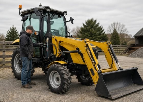
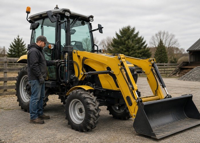
When a tractor hydraulic coupler will not connect, stop forcing it. The most common causes are trapped pressure on the tractor or attachment side, a sleeve that is not fully retracted, dirt on the mating faces, incompatible coupler profiles, damaged seals, or a hose that is twisted and pushing the plug out of alignment. The safe solution is to lower the attachment, shut the machine down, relieve stored energy by the model procedure, clean and inspect both halves, and then make one straight connection.
Hydraulic oil can penetrate skin through a leak that is almost invisible. Keep hands away from suspected leaks and never loosen a fitting merely to make a coupler easier to push. The NIOSH hydraulic safety guidance explains why an injection injury needs immediate specialist treatment even when the wound looks small.
Record which connection fails, whether the problem occurs after the implement sits in sun, whether the loader was lowered before shutdown, and whether the male tip can be pushed at all. A connection that is easy cold but impossible after transport points toward thermal expansion or residual pressure. A sleeve that feels gritty or will not travel its full stroke points toward contamination or mechanical damage.
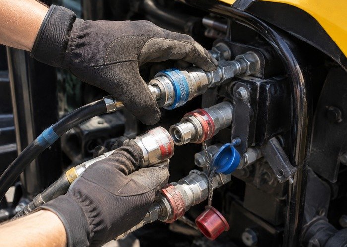
Move to level ground, lower the loader and attachment completely, place the transmission in neutral or park, set the brake, stop the engine, remove the key, and wait for motion to stop. Keep people clear because loader arms or an attachment can settle as pressure is relieved. If the machine provides a mechanical loader support, use it only as the manual specifies; it does not replace lowering the attachment for coupling.
Follow the tractor operator manual. A common procedure is to turn the key to the run position without starting, then move the loader joystick through every direction several times. Some systems have a pressure-relief button or require a different order. The tractor operator-guide example shows why hydraulic lines should be connected with the tractor off, but its exact sequence belongs only to the covered model.
An attachment disconnected while its cylinders were loaded can trap pressure in the hoses. Sunlight can warm the oil and raise that pressure further. Set the attachment on stable ground so no cylinder is supporting weight. Use the attachment maker’s approved relief device, pressure-relieving coupler, or storage procedure. Never press a coupler tip against steel, strike it, or cover it with a rag and force it open.
If the attachment has a movable function that can be repositioned safely with the machine disconnected, follow its manual. Some owners install approved connect-under-pressure couplers or a dedicated relief tool; verify pressure rating, oil compatibility and profile. Do not add an un-rated valve or fitting that could release a hose or expose an operator to oil.
Wipe the female body, sleeve, locking balls, male tip and dust caps with lint-free material. Look for grit, rust, paint, dents, flattened noses, cut O-rings, displaced backup rings and corrosion. A dirty coupler can refuse to lock, restrict flow after connection, or carry contamination into the tractor valve and attachment motor.
Confirm both halves are the same standard, nominal size and pressure rating. Agricultural, flat-face and other profiles may look close but will not mate correctly. Compare part numbers and dimensions rather than color alone. The hydraulic-system safety overview reinforces cleanliness, hose inspection and stored-energy control.
Support the hose so its weight does not cock the plug. Pull the female sleeve fully back if required, align the male tip on the same axis, and push with a firm continuous motion until the lock completes. Release the sleeve and perform the manufacturer’s pull-back check. Do not use pliers on sealing surfaces or brace a coupler against a tire.
If it connects only when the hose is twisted, stop and correct routing. A hose must have adequate bend radius and enough length through full loader travel without rubbing, stretching or pinching. Review the tractor hydraulic flow and attachment guide to confirm hose, flow and return requirements before operation.
With pressure confirmed relieved, exercise the empty sleeve by the service procedure. It should move smoothly and return. A seized sleeve, broken spring, damaged locking ball or deformed male groove requires replacement. Do not grind, file or remove balls to make mismatched parts connect.
Check the mounting bracket. A bent panel can place side load on the female body. Inspect hose-end adapters for looseness only after pressure is safely removed. Replace complete damaged components using specified seals and torque. The agricultural equipment safety guide supports isolation and safe maintenance around powered machinery.
If the coupler locks but the attachment will not move, verify hose pairing, auxiliary valve selection, flow mode, return path and any case drain. A valve in detent or a blocked return can retain pressure and create heat. Do not reverse hoses until the attachment manual confirms what each port does.
Compare symptoms with the tractor hydraulic valve selection guide and the tractor loader inspection checklist. A connection problem is mechanical at the interface; a connected attachment that is slow, weak or one-directional needs a flow-and-pressure diagnosis.
The following video demonstrates a common trapped-pressure complaint and a short field remedy. It is useful for recognizing the symptom, but not every step shown is approved for every tractor or coupler.
Use the operator manual as the controlling procedure. Lower the attachment and remove stored energy before touching the connection.
Do not loosen a pressurized fitting or force a poppet. Select an approved relief method that contains oil and keeps skin away from the release path.
After pressure is relieved, clean the faces again because an attempted connection can transfer grit. Align the couplers and confirm the sleeve locks.
Start the tractor only from the seat, run at low engine speed and cycle the attachment without load. Stop immediately for leakage, hose movement or abnormal noise.
Recheck oil level using the specified method. A cylinder or long hose can change reservoir level after connection and purging.

| Observation | Likely cause | Safe next step |
|---|---|---|
| Tip will not enter | Residual pressure or profile mismatch | Relieve both sides and verify part numbers |
| Sleeve will not retract | Dirt, corrosion or damage | Clean and inspect with pressure removed |
| Locks but leaks | Seal, nose or alignment damage | Stop, depressurize and replace parts |
| Connects cold, not hot | Thermal pressure rise | Use approved storage/relief method |
| Connected but no function | Wrong ports, valve, flow or return | Trace the hydraulic circuit |
Label hose pairs, fit clean caps, store attachments with cylinders relaxed where the manual permits, and protect couplers from impact. Add the checks to the tractor attachment maintenance checklist. The goal is a clean, pressure-free connection and a controlled low-load test.
A recurring coupling problem often begins at the previous shutdown. Train operators to place the attachment on stable level ground, relax cylinder load, return controls to neutral, lower the loader, stop the engine and move the joystick through the approved relief sequence before disconnecting. Fit clean caps immediately. Do not leave a heavy hose hanging from its male tip, because side load can scar the nose and deform the locking groove.
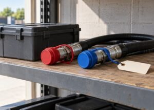
Create a hose map for each loader attachment. Photograph the correct pair, mark pressure and return with durable sleeves, record the coupler standard and list whether a tank return or case drain is required. Keep the map near the tractor rather than relying on color after caps fade. An incorrect return connection can make an attachment seem impossible to connect or can create damaging back pressure after it locks.
Check storage conditions. A cylinder left extended in direct sun contains a larger heated oil volume, and a heavy attachment resting on a cylinder can retain load. Protect hose ends from rain, dust and impact. Use a rack that supports bend radius and keeps fittings off the floor. If thermal pressure is common, ask the attachment or coupler supplier for a rated storage or connect-under-pressure solution instead of improvising.
When diagnosing, measure rather than push harder. A rated pressure gauge or approved diagnostic coupler can confirm which side retains pressure. Record ambient temperature, oil temperature, attachment position and the time since shutdown. Compare the result after following the correct relief sequence. If pressure returns without load or heat, inspect the directional valve, cylinder leakage path or a blocked hose.
Coupler seals need the correct material for the oil, temperature and pressure. A seal that swells, extrudes or hardens may increase connection force before it leaks. Replace the specified seal kit only after inspecting the metal nose, sleeve bore and locking balls. A new O-ring cannot repair a dented tip or mismatched profile.
During the first operational test, keep the engine at low speed and cycle every attachment function over a short safe range. Watch the hoses from a protected position for twisting, rubbing and tension. Lower the attachment and shut down before correcting routing. Recheck the sleeve lock and inspect for a wet ring that may indicate a seal leak.
Record the final outcome: whether pressure relief restored connection, which component was replaced, oil lost and replenished, and whether the attachment worked in both directions. A complete record helps distinguish operator sequence, thermal pressure and progressive coupler damage the next time the complaint appears.
Before buying a replacement, provide the supplier with the tractor and loader serial numbers, coupler location, male and female part numbers, thread or port type, nominal body size, profile, pressure rating, seal material and clear photographs. State whether the failure is insertion, sleeve travel, locking, leakage or restricted flow. A generic description such as half-inch coupler may identify several incompatible families.
Ask whether a proposed replacement mates with the existing half, whether both halves should be replaced as a matched pair, and whether an adapter changes flow capacity or pressure drop. Confirm dust-cap fit and mounting dimensions. If the attachment fleet uses mixed standards, plan a controlled conversion rather than adding chains of adapters that increase leak points and side load.
When the machine returns to work, include coupler inspection in the walk-around. A cap hanging open, wet dust ring, hose abrasion or bent bracket is cheaper to correct before connection force rises. Keep a lint-free cleaning kit and approved absorbent material with the tractor, and dispose of oil-contaminated waste according to local requirements.
The closing test is simple but disciplined: pressure relieved, faces clean, profiles matched, sleeve locked, pull-back check passed, hoses free through full movement, function normal in both directions, no leaks and oil level correct. If any item fails, lower the attachment and correct it before production work.
Recheck the same connection after the oil reaches normal temperature. Warm seals, hoses and trapped oil can behave differently, and a small restriction may not appear during a short cold test. Shut down, lower the loader, relieve pressure and confirm the coupler still disconnects and reconnects normally without excessive force. Compare the exact sequence with the machine maker’s published coupling instructions, because relief steps and sleeve operation differ by model.
If connection force rises again, compare both sides and inspect whether the attachment cylinder settled or the hose warmed in direct sun. Record the change rather than opening a fitting. Repeat the approved relief step and have the valve or coupler serviced if pressure returns without an external load. If connection is normal but the loader remains weak, continue with the tractor hydraulic pressure test guide instead of replacing another coupler.
No. Impact can damage the nose, sleeve and locking parts and may release high-pressure oil.
That circuit may contain trapped cylinder load or thermal pressure. Identify the hose and use the attachment’s approved relief procedure.
Yes. Different profiles and tolerances can look similar. Match the standard and part number.
No. The mating nose is not a threaded seal. Service adapters only as specified and keep compound out of the hydraulic system.
Stop for damaged couplers, repeated pressure trapping, leaking hoses, failed valves or any procedure requiring opening a pressurized circuit.