Telephone/WhatsApp:+86 156 2656 0610

Telephone/WhatsApp:+86 156 2656 0610
Email:info@seekmach.com

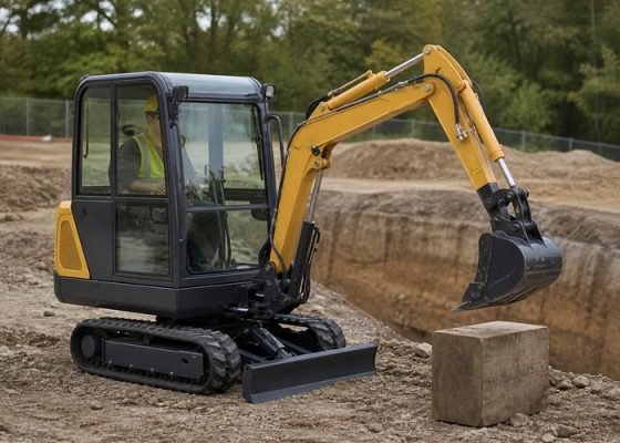
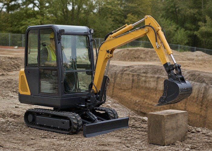
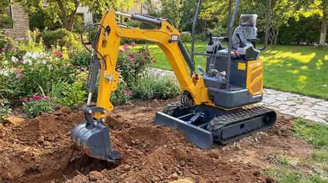
A mini excavator boom, stick, or bucket that moves without joystick input has cylinder drift, but drift does not automatically prove that the cylinder piston seal has failed. Oil can leave a loaded chamber through the main control valve, a port relief valve, a load-holding valve, a hose or fitting, or an external rod seal. Temperature, air, linkage position, and the weight of the attachment also change the result.
Never work beneath raised equipment. Move the excavator to a hard level surface in a clear area, lower the blade, remove material from the bucket, keep bystanders away, and follow the operator and service manuals. Use the hydraulic lock, parking brake, shutdown, and support procedure specified for the machine. A drifting boom is a dropped-load hazard, not a reason to reach under the linkage.
The goal is to produce a repeatable number under a defined position and temperature, then isolate the circuit logically. The new measurement can be added to the mini excavator maintenance checklist so future changes are visible before productivity falls.
Observe whether the boom lowers, the stick opens or closes, the bucket uncurls, the dozer blade settles, or several functions move together. Note whether drift occurs with the engine running, after shutdown, only when hot, only with a loaded bucket, or only in one linkage position. Record hydraulic oil temperature, elapsed time, attachment, coupler, bucket mass, and any auxiliary tool.
Distinguish linkage settling from continuing movement. Pin and bushing clearance may produce a small initial change when load direction reverses. Track sinkage or tire movement on an uneven surface can also change the bucket height. Measure cylinder length or rod movement rather than judging only the bucket edge.
Stop using the machine if drift is rapid, unpredictable, accompanied by an external leak, or affects safe control. Do not rely on the joystick neutral position to support a load. OSHA’s heavy-equipment struck-by guidance reinforces exclusion zones and machine-control discipline around mobile equipment.
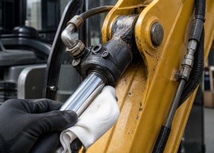
Clean the cylinder rod, gland, fittings, hoses, valve area, and swivel before testing. A thin lubricating film on a rod may be normal; a wet streak, drip, or oil collecting dust is evidence. Inspect the chrome for scoring, rust, dents, and transferred material. Damage that passes through the rod seal can cause rapid repeat leakage after a simple reseal.
Check pin retainers, bushings, linkage cracks, coupler lock, and bucket attachment. Excessive play can exaggerate perceived drift and create shock loads. If the quick coupler or attachment is suspect, use the mini excavator parts ordering guide to document model, serial number, measurements, and photographs before ordering.
Never wipe a pressurized leak with a bare or gloved hand. Hydraulic injection can penetrate skin and requires emergency medical care. Follow NIOSH hydraulic safety guidance, release stored pressure, and use cardboard or another approved method when the manual calls for leak detection.
Warm the oil to the service-manual range through normal operation, not by holding a function over relief. Park in the specified test position. Some manufacturers measure pin-to-pin cylinder length; others mark a reachable section of rod. Use the exact boom, stick, bucket, blade, engine, and control positions given for the model.
Measure once, shift controls to neutral, engage the parking brake, apply the hydraulic lock, shut down if specified, and wait the stated interval. Repeat at exactly the same points. Caterpillar’s hydraulic technical analysis guide describes a three-minute drift check and emphasizes comparing the number with the machine specification.
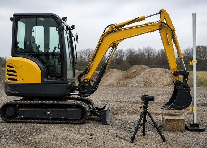
Repeat the test two or three times. A camera aimed at a ruler can help confirm timing while everyone remains outside the hazard zone. Do not place a person between the attachment and a wall, trench, trailer, or machine. If the required position cannot be measured from the ground safely, stop and use a qualified service facility.
Hot oil is less viscous, so clearances in a worn valve or cylinder may pass more leakage. A machine that holds cold but drifts beyond specification hot needs hot testing. Record ambient temperature and oil temperature rather than describing the system as merely warm. Use an infrared thermometer at consistent clean surfaces only as a comparison; service temperature comes from the machine sensor or specified test method.
A heavier attachment creates more cylinder pressure and may increase leakage. Do not use a random load to speed the test. The service procedure may require an empty bucket or a defined load. Never suspend personnel or use an excavator as an uncertified lifting device.
Air can create spongy or delayed motion after hose, cylinder, or oil service. Follow the manufacturer’s bleeding and cycling procedure. Cavitation noise, foamy oil, erratic speed, or low reservoir level must be corrected before drift numbers are trusted. Review oil and inspection items in the mini excavator fluid evidence guide, while remembering that final drive and hydraulic reservoirs are separate systems.
In a double-acting cylinder, the rod side and cap side have different volumes. Internal piston leakage may allow pressures to equalize without providing an external path for enough oil to leave the cylinder. Depending on load, geometry, port connection, and valve leakage, a failed piston seal may cause weak force, heat, or slow cycle time without simple downward drift.
The main control spool can leak from a work port to tank or another passage. A port relief or anti-cavitation valve may not seat. A boom holding valve, hose-burst valve, or counterbalance valve may leak or receive an incorrect pilot signal. Hoses can expand slightly, but continuing movement beyond specification requires circuit diagnosis.
A service procedure may isolate a cylinder or swap controlled connections to distinguish components. Do not cap a loaded line, block a valve, or loosen a fitting to see whether oil appears. Trapped pressure can move the machine or inject fluid. The Komatsu service-manual example shows that cylinder packing, control valve, and drift-prevention valve must be separated with a defined test.
Measure function cycle time at the specified oil temperature, engine speed, power mode, and linkage position. A slow boom in both directions may indicate pump flow, restriction, spool travel, or cylinder friction. Normal speed with excessive neutral drift focuses attention on load-holding leakage rather than general pump output.
Compare left and right boom cylinders only if the machine uses a matched pair and the manual permits measurement. Unequal rod temperature, leakage, or stroke can reveal imbalance, but do not loosen lines. Check diagnostic codes and pilot pressure before adjusting a main or port relief valve.
For lifting concerns, confirm the permitted configuration using the mini excavator lift chart guide. A lift chart does not authorize operation with a drifting circuit. Remove the machine from lifting service until control meets specification.
The following Caterpillar video shows hydraulic technical analysis tests, including cylinder drift and cycle-time measurements. It demonstrates the discipline of setting temperature, linkage position, timing, and measurement points. Values for the machine in the video must not be applied to another excavator.
Before testing, obtain the operation and maintenance manual and the hydraulic testing section for the exact serial number. Clear enough space for full linkage movement, confirm overhead clearance, and keep all observers out of the swing and attachment zones.
Use a timer and marked measurement points. Record oil temperature before and after the sequence. If a result changes significantly between repetitions, inspect setup, air, attachment movement, ground stability, and operator input before interpreting component condition.
Do not stall functions against relief longer than the manual allows. Relief testing rapidly creates heat. Pressure gauges, adapters, and hoses must be rated for the circuit and installed by a qualified person.
| Evidence | Likely direction | Next controlled check |
|---|---|---|
| Visible oil at rod gland | Rod seal or rod damage | Clean, inspect rod, measure loss, follow reseal criteria |
| Drift hot but acceptable cold | Clearance leakage or wrong oil | Repeat at specified temperature; valve/cylinder isolation |
| One function drifts, cycle time normal | Work-port, holding valve, or cylinder circuit | Model-specific isolation test |
| Several functions drift | Main valve condition, oil, temperature | Compare circuits and diagnostic pressure |
| Slow cycle and weak force | Flow, pressure, restriction, pump, leakage | Specified flow and pressure test |
If a cylinder is removed, cap every line and port immediately. Protect the rod from impact and contamination. Inspect barrel, piston, wear bands, gland, rod straightness, surface finish, and threads rather than installing seals into damaged parts. Use correct seals, assembly tools, lubricant, torque, and cleanliness.
If the valve is repaired, identify the exact spool, relief, holding valve, and shims before disassembly. Do not interchange cartridges or alter settings. Flush only through an approved contamination-control plan. A general hydraulic fluid-condition overview helps relate water, particles, viscosity, and heat to repeat failures.
After repair, bleed and cycle as directed, inspect for leaks, warm the oil, and repeat the original drift and cycle-time tests with the same attachment and position. Record before and after measurements. Inspect related slew and linkage play with the mini excavator slew-ring play guide so unrelated movement is not mistaken for cylinder drift.
Prepare a circuit map before connecting gauges or removing lines. Mark the pump, main spool, work ports, port reliefs, anti-cavitation valves, any boom-holding valve, cylinder chambers, and return path. Then list what each test can prove. A pressure decay at one port may show that oil is leaving the loaded chamber, but it does not automatically reveal whether it crosses the piston or returns through a valve.
Compare related symptoms. If the boom drifts but retains normal lift force and cycle time, a neutral load-holding leak is more likely than a broad pump-flow problem. If the same cylinder is weak in one direction, runs hot, and has abnormal cycle time, internal bypass becomes more plausible. If several spools drift after the oil warms, investigate valve condition, contamination, and oil specification before rebuilding every cylinder.
A technician may use manufacturer-approved blocking, pressure trapping, or component substitution to isolate the path. The important rule is that every test must maintain a safe support and a controlled escape route for oil. Never improvise plugs on a raised boom. Even a small volume released from a high-pressure chamber can move the linkage rapidly.
Seal life depends on more than the new seal kit. Check rod alignment, pin wear, side loading, surface finish, wiper condition, oil cleanliness, cooling, and attachment practices. A bent rod or loose bushing pushes the gland sideways and can destroy a replacement seal. Dirt entering through a damaged wiper circulates through valves and cylinders.
Sample oil if failure produced debris or heat. Use a clean sampling point and compare particle, water, viscosity, and wear results with the correct limits. Replace filters and clean reservoirs only as directed; indiscriminate flushing can move contamination into sensitive valve passages. Recheck the drift number after the first work interval to confirm that the repair remains stable.
Retain the worksheet with the machine service history so later technicians can compare the same temperature, position, timing, and attachment instead of starting from an uncertain baseline.
Manufacturers usually publish a permitted amount for a specific temperature, position, load, and time. Only that specification decides whether the measured drift is acceptable.
No. Oil may leak through the control valve, port relief, holding valve, hose, fitting, or external seal. Isolate the circuit before ordering parts.
No. A loaded circuit can retain dangerous pressure and move unexpectedly. Use rated test equipment and the manufacturer’s isolation method.
Greater load raises cylinder pressure and can increase leakage through existing clearances. Test only with the specified attachment and load.
Stop for rapid or unpredictable movement, external leakage, damaged rods or hoses, failed load-holding equipment, unsafe lifting control, or any result beyond the service limit.