Telephone/WhatsApp:+86 156 2656 0610

Telephone/WhatsApp:+86 156 2656 0610
Email:seekmach@gmail.com


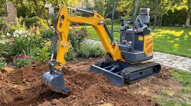
Most excavator operators don’t lose money the moment a machine breaks down — they lose it in the weeks of slow, degraded performance that precede the failure nobody saw coming.
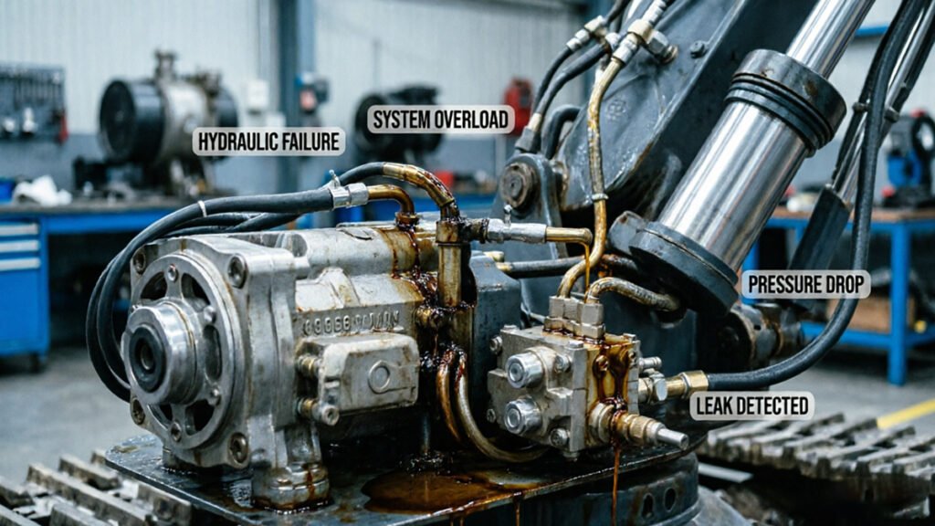
Hydraulic failure rarely announces itself. It erodes quietly, through pressure loss, internal wear, and deferred maintenance — until a job-site shutdown becomes unavoidable.
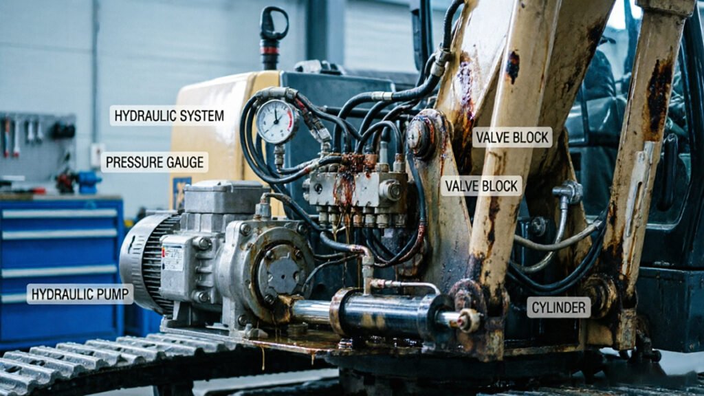
Understanding why requires stepping back from the pressure gauge and looking at the physics underneath it. Hydraulic systems operate on the principle of energy conversion: the pump transforms mechanical energy into pressurized fluid, and that fluid drives every cylinder, motor, and valve on the machine. As research into excavator fault diagnosis confirms, pressure loss directly correlates to mechanical inefficiency — indicating every drop in system pressure results in a measurable loss of productive work output, not just a number on a dial.
The concept of ‘state monitoring’ reframes how experienced technicians approach excavator hydraulic repair. Rather than waiting for a catastrophic event, state monitoring treats real-time system data — cycle times, fluid temperature, operating pressure — as a continuous diagnostic picture. Subtle deviations from baseline values are early indicators of wear, not background noise to ignore. As field troubleshooting guides note, a slow or weak hydraulic system almost always has a traceable root cause that predates the visible symptom.
Internal wear is the engine of pressure loss. Worn pump components, degraded seals, and contaminated fluid all reduce volumetric efficiency — the system works harder to deliver less. Understanding how hydraulic longevity connects to maintenance intervals makes this concrete: contaminated fluid alone is the leading cause of pump failure, a repair that quickly costs thousands of dollars.
That cumulative damage starts long before a gauge ever moves into the red — which is why recognizing the early symptoms matters so much.
Clogged hydraulic filter symptoms rarely announce themselves loudly — they manifest as subtle performance drift that most operators attribute to worn attachments or operator error, not a filter on the verge of failure.
According to Machinery Lubrication and Noria Corporation, over 70% to 90% of all hydraulic system failures trace back to fluid contamination. The filter is your first and last line of defense against that statistic — and when it’s compromised, the consequences ripple through every hydraulic circuit on the machine.
Watch for these early warning signs before a clogged filter becomes a catastrophic one:
Understanding the bypass mechanism is critical here. Modern filters include a pressure-relief bypass valve — a safety feature that activates when differential pressure across the filter exceeds a set threshold (typically 25–75 psi). When this valve activates, unfiltered, contaminated fluid bypasses the filter element entirely and circulates through your pump, valves, and cylinders. The machine keeps running, but the damage accumulates invisibly. Much like how microscopic particulates destroy precision components in diesel fuel systems, bypassed hydraulic contaminants attack internal surfaces at a level no external inspection can catch.
Suction vs. return filter clogs behave differently. A clogged suction filter restricts fluid entering the pump, causing immediate cavitation, heat, and noise — symptoms that are hard to miss. A clogged return filter, however, creates back-pressure that can blow seals and bypass contamination more silently, making it the more deceptive failure mode of the two.
Manufacturing quality plays a role before a drop of fluid ever enters the system. Facilities operating under controlled environments with rigorous cleanliness standards — often measured across tens of thousands of square meters of production space — apply strict particle-count protocols during component assembly. This prevents initial contamination from being introduced at the factory level, meaning the filter’s workload begins lower from day one.
Understanding what’s happening inside the filter points directly to a deeper question: why does fluid lose its ability to do useful work in the first place? That answer lives in the pump itself — specifically in how volumetric efficiency degrades over time.
Volumetric efficiency is the single most telling metric of hydraulic pump health — yet most operators do not measure it until damage has occurred.
Volumetric efficiency describes how closely a pump’s actual output matches its theoretical displacement. A new pump running at peak condition typically operates at 90–95% efficiency. As internal components wear, that number quietly erodes. The pressure gauge may still read normal, which is exactly why the previous section’s symptom checklist matters — by the time the gauge reflects a problem, volumetric efficiency has often already dropped to a point where real work capacity is measurably compromised.
Internal leakage is the primary culprit. Inside a piston or gear pump, microscopic clearances between rotating components are engineered to allow a controlled film of fluid for lubrication. Over time, wear widens those clearances. Fluid that should be pushing your bucket cylinder instead bypasses internally — cycling back to the reservoir as heat instead of performing work. According to Hydraulics & Pneumatics, excessive heat is a leading indicator of this internal bypass within hydraulic cylinders or control valves. You’re not losing pressure in a dramatic, obvious way. You’re losing volume, quietly.
Pro Tip — Infrared Testing: Point an infrared thermometer at the pump housing, control valve block, and individual cylinder barrels after 20–30 minutes of operation. Temperatures running more than 20°F above adjacent components typically signal internal bypass, not just ambient heat soak. This non-invasive test costs nothing beyond a $30 tool and can isolate a failing component before it triggers a full system shutdown. For context on how cylinder rod seal wear compounds this problem, see this breakdown of mini excavator relief valve behavior.
Tight manufacturing tolerances are why OEM and high-spec ODM components hold efficiency longer. Components machined to tighter specifications maintain that critical clearance film without allowing bypass-level gaps to develop prematurely. Cheaper alternatives often ship with looser tolerances that accelerate wear curves significantly.
One practical note: operators troubleshooting sluggish response sometimes ask how to bleed air from an excavator hydraulic system before suspecting volumetric loss — although air entrainment does produce similar symptoms, the diagnostic approach differs considerably. That distinction deserves its own careful treatment, which the next section addresses directly.
Spongy, unresponsive controls almost always trace back to one root cause: unwanted air in the hydraulic circuit, either through aeration or cavitation.
Aeration and cavitation are not the same problem, and treating one as the other will cost you time and components. According to Mobile Hydraulic Tips, these two phenomena are the primary drivers of spongy controls and the loud banging noises operators often misattribute to mechanical failure. Aeration occurs when air enters the fluid from outside — typically through a loose suction line fitting or a degraded reservoir breather. Cavitation, by contrast, happens when the pump creates a vacuum so severe that dissolved gases come out of solution inside the fluid itself, collapsing violently against internal surfaces. Cavitation damage is irreversible and directly destroys hydraulic pump volumetric efficiency over time.
Bleeding the system correctly follows a sequence — skip a step and you reintroduce the problem.
Seal integrity is where long-term air exclusion is won or lost. Components that meet recognized certification standards maintain tighter dimensional tolerances, which means fittings seat properly and seals hold under thermal cycling. Cutting costs on replacement fittings is a common pattern that leads operators back to bleeding the system within weeks.
With air eliminated from the circuit, the next logical checkpoint is the component that governs maximum system pressure — and how a misadjusted relief valve can mimic almost every symptom covered so far.
The relief valve is the unsung guardian of your excavator’s hydraulic system — and when it fails silently, the entire machine pays the price.
“The hydraulic pump is the heart of the machine, but the relief valve is its primary protector.” — Construction Equipment Magazine
That quote cuts straight to the point. Excavator pressure testing without including the main relief valve in your diagnostic sequence is like checking a patient’s heart rate while ignoring their blood pressure. You’re only getting half the picture.
Relief valve failure rarely announces itself dramatically. Instead, it disguises itself as performance degradation. Two distinct symptom patterns typically emerge: stalling under load, where the system can’t sustain enough pressure to complete a work cycle, and loss of breakout force, where the bucket or arm feels weak even though the gauge reads normal. The first points to a valve opening too early — bleeding off pressure before the actuator can do its job. The second often means the valve is set too low relative to the OEM specification, robbing the machine of working force without triggering any obvious alarm.
Safety protocols for high-pressure testing are non-negotiable. Hydraulic circuits on modern excavators routinely operate between 3,000 and 5,000 PSI. Before connecting a test gauge, always relieve residual system pressure, use rated fittings that match your circuit’s peak pressure, and keep bystanders clear of hose connections. Fluid injection injuries from hydraulic leaks at high pressure are classified as medical emergencies — the entry wound can appear minor while internal damage is severe.
Daily maintenance logs should capture relief valve behavior alongside fluid levels and filter condition. Note any change in dig force, cycle times, or unusual pressure spikes. Over time, this log becomes the baseline that makes early fault detection far more reliable — and keeps small calibration drift from becoming a costly failure.
Identifying what the relief valve is telling you is only one piece of the diagnostic puzzle. The next step is moving from symptom recognition to structured fault logic — combining instruments, documentation, and systematic exclusion to pinpoint exactly where your system is breaking down.
Systematic fault logic diagnosis transforms hydraulic troubleshooting from educated guesswork into a repeatable, evidence-driven process that reliably identifies root causes before a single fitting is loosened.
The shift from trial-and-error to logical exclusion is the single most impactful upgrade a technician can make. Random component swapping wastes time and masks underlying problems. According to the Art and Technology Journal, state monitoring and logical diagnosis reduce repair time by identifying the root cause before disassembly begins — a critical advantage when a machine sitting idle costs real money per hour.
Flow vs. pressure analysis is where this framework pays off most visibly. A slow actuator is a classic diagnostic fork in the road: the symptom could stem from insufficient flow, inadequate pressure, or both. In practice, pressure alone tells an incomplete story. A gauge reading within spec doesn’t rule out a worn pump delivering low volume — it just means the circuit can still build resistance. Running a flow meter and pressure gauge in tandem closes that gap. If pressure holds but flow is below spec, the pump or control valve is the prime suspect. If both readings drop, the problem is likely systemic — possibly hydraulic fluid contamination degrading pump clearances and valve response simultaneously.
Technical documentation becomes indispensable at this stage, especially with OEM and ODM machinery where component tolerances vary significantly between builds. Factory service manuals define the exact flow rate and pressure thresholds a given actuator requires. Without those benchmarks, even accurate gauge readings are hard to interpret. Understanding how engine output relates to hydraulic pump capacity — a relationship explored in detail when looking at how pump load affects output — helps frame whether a deficit is mechanical or operational in origin.
With the diagnostic framework established, the next step is putting it into practice — and few things accelerate that learning curve faster than seeing real-world hydraulic faults diagnosed visually.
A disciplined visual inspection often catches what pressure gauges and fault codes miss — and it costs nothing but time.
Before reaching for a diagnostic tool, walk the machine and read what it’s showing you. Two of the most telling clues are hose weeping and rod scoring. Hose weeping — that faint oil film collecting at fittings or along braid — signals micro-fractures or fitting fatigue under cyclic pressure. Rod scoring, visible as fine longitudinal scratches on a cylinder’s chrome surface, tells you the wiper seal has already been compromised by contamination. Both signs precede catastrophic failure, and both are visible in a five-minute walkaround.
Oil color and clarity deserve equal attention. Healthy hydraulic fluid is amber and transparent enough to read print through. According to Machinery Lubrication, cloudy oil indicates water contamination, while foamy oil indicates air ingestion — two conditions that accelerate pump wear faster than almost any other factor. Milky, opaque fluid means an emulsion has already formed; at that point, a fluid change and system flush are non-negotiable before any further diagnosis.
The YouTube walkthrough embedded below demonstrates these visual cues in a live repair context — watch specifically for how the technician pauses on each fitting before cracking a line, and how fluid color is assessed at the reservoir before the pump is even touched.
[Visual placeholder: YouTube embed — Pressure Problems and Irregularities? Common Causes Explained]
One practical advantage that’s easy to underestimate is factory-direct support. Machines sourced through direct channels — like compact excavators with matched hydraulic specs — come with access to OEM documentation that maps component tolerances, relief valve settings, and fluid specs precisely. That context turns a visual finding into an actionable diagnosis rather than a guess.
The patterns covered across this article — from cavitation signatures to fault logic and now visual cues — all point toward a common set of principles worth consolidating before you head back to the machine.
Hydraulic longevity comes down to four disciplines — and operators who master them routinely double or triple the service life of expensive components.
Contamination control is the single highest-leverage habit you can build. Particle contamination is the root cause behind the majority of premature hydraulic failures, and the math is unforgiving: according to Noria Corporation, proper filtration alone can extend component life by up to 4x. That means skipping a filter change isn’t a minor shortcut — it’s a decision that compounds into thousands of dollars in accelerated wear. Every time a bypass valve opens because a clogged filter is ignored, unfiltered fluid flows directly through precision pump internals with tolerances measured in microns.
Never dismiss spongy or sluggish controls as a minor nuisance. That soft, unresponsive feeling in the joystick is a classic early-warning signal of cavitation — a condition where vapor bubbles form in low-pressure zones and then implode against metal surfaces with enough force to pit and erode pump components. Cavitation rarely announces itself loudly at first. By the time whining noises and visible performance loss appear, meaningful damage has already occurred. Catching the spongy-control symptom early and tracing it back to a suction restriction, low fluid level, or viscosity mismatch can save a pump replacement that routinely runs $2,000–$6,000.
Pressure testing must come before parts purchasing. As covered in the fault logic section, swapping components based on symptoms without first confirming pressure readings is a costly gamble. A field troubleshooting guide for weak hydraulic systems reinforces that systematic pressure verification consistently pinpoints whether a problem is originating at the pump, relief valve, or actuator — saving both time and unnecessary parts spend.
Adherence to ISO and CE maintenance standards is non-negotiable for factory-direct machinery. It’s worth noting that engine horsepower doesn’t directly equal hydraulic output — as explored in how hydraulic capacity scales with machine design — which is why manufacturer-specified service intervals exist to keep the entire power transfer chain operating within design tolerances.
If these takeaways raise specific questions about your maintenance routine or symptoms you’re already seeing, the FAQ section ahead addresses the most common hydraulic concerns directly.
Excavator owners ask the same four questions repeatedly — and the answers reveal just how preventable most hydraulic failures really are.
How often should I change hydraulic filters on a new excavator?
Most manufacturers specify an initial filter change at 50–100 hours on a new machine, followed by intervals of 500 hours or every six months under normal operating conditions. Break-in wear generates fine metallic particles that load the filter quickly, so skipping that first service is a costly shortcut. Always follow the OEM schedule as a floor, not a ceiling — dirty or dusty jobsites may demand more frequent changes.
Can I mix different brands of hydraulic oil?
Technically, yes. Practically, it’s a risk not worth taking. As Hydraulics & Pneumatics notes, mixing oils with incompatible additive packages can lead to sludge formation and filter plugging — issues that accelerate pump wear and restrict flow throughout the entire circuit. The safest rule: drain the system fully before switching fluid brands or viscosity grades. If a top-off is unavoidable in the field, use the smallest quantity possible and schedule a full fluid change at the next service interval.
What is the first sign of hydraulic pump failure?
Sluggish cycle times under load almost always appear before any other symptom. The pump begins bypassing internally, flow drops, and the system compensates by running longer or hotter. Unusual whining or cavitation noise during startup is a close second warning sign, as this field troubleshooting guide explains in detail. Catch either signal early and a repair is still on the table; ignore both and replacement becomes inevitable.
How do I know if my relief valve is set too low?
The clearest indicator is an attachment or boom that stalls or moves weakly under rated load — even though the engine and pump appear healthy. A technician can confirm it by measuring circuit pressure against the manufacturer’s specification. Relief valves drift over time, and a setting even 200–300 PSI below spec can noticeably reduce digging force without triggering any fault codes.